Built for intensive use
The 120–720 kW portfolio serves demanding, multi-bay sites.

High-power systems
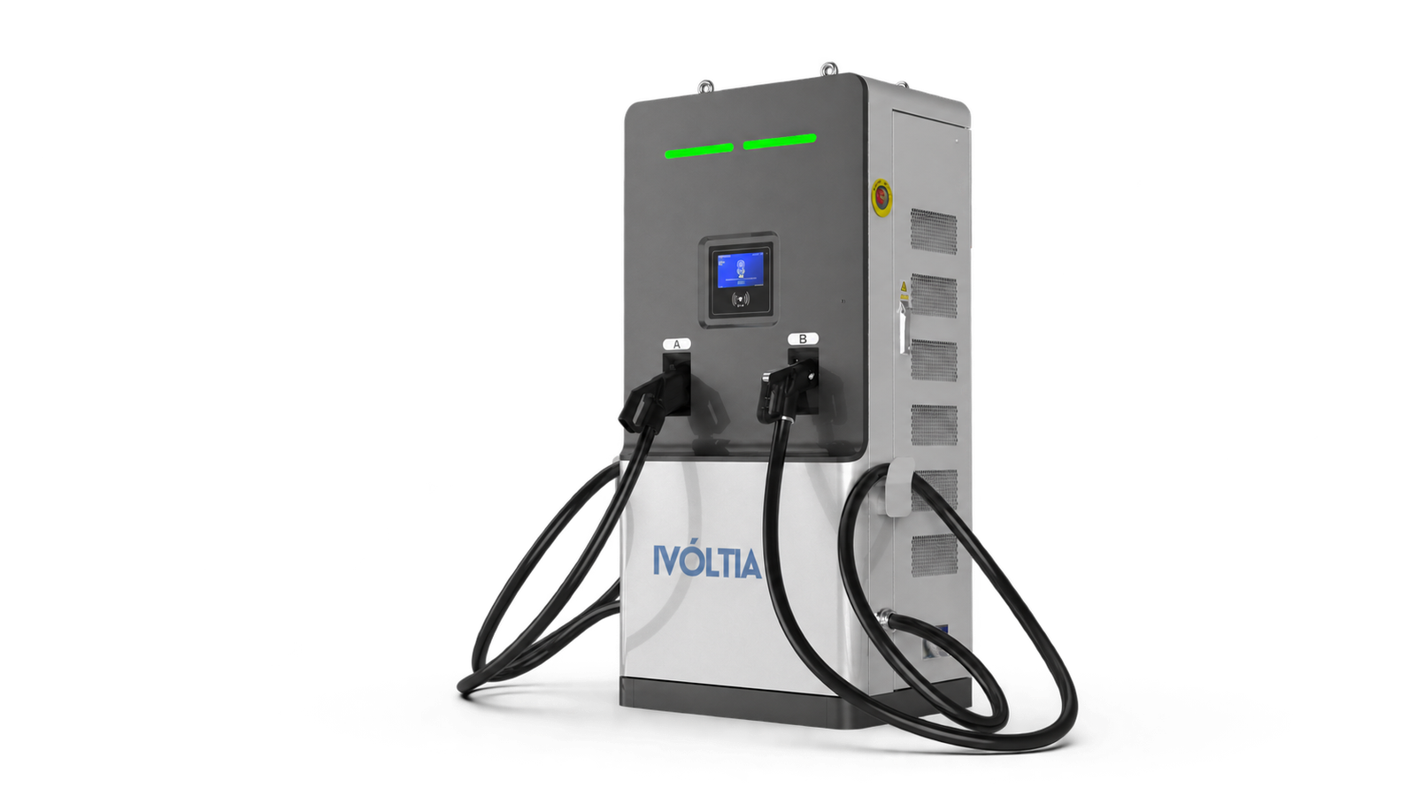
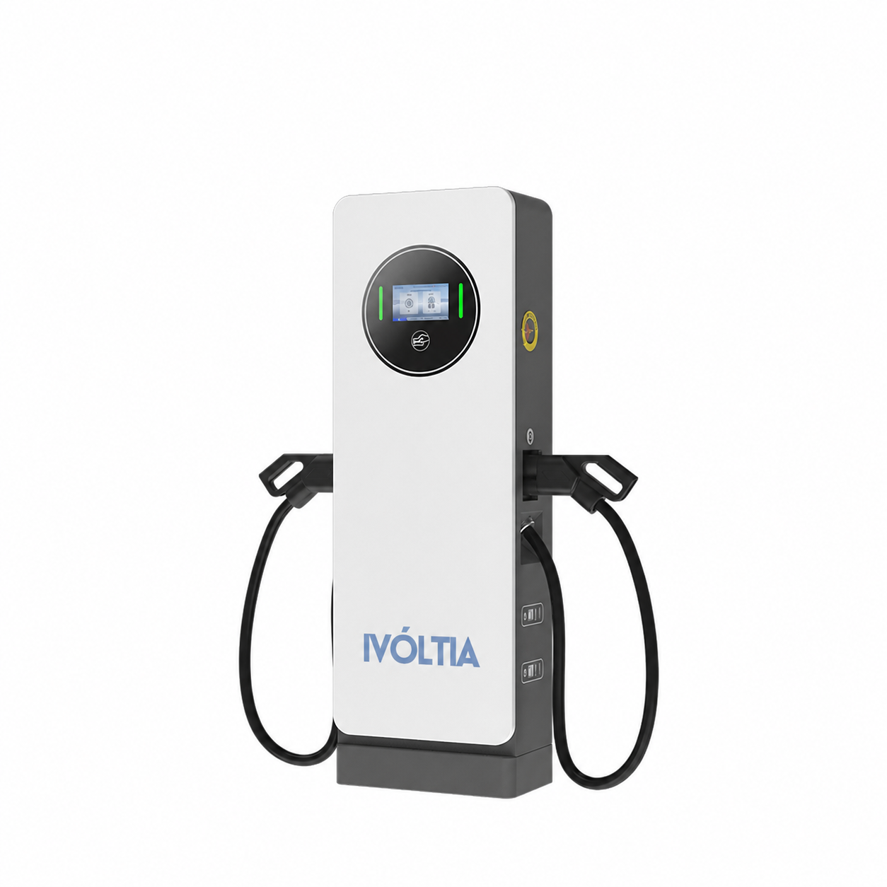
120–240 kW integrated chargers and 240–720 kW distributed systems for high-utilization sites.
PRODUCT IN CONTEXT
Integrated and distributed DC systems are planned around vehicles, charging windows and site capacity.
Size electrical supply against the duty cycle.
Distribute available output across bays.
Plan service access and thermal conditions.
PRODUCT FACTS
Compare the numbers that affect vehicle fit, site design and operations.
| Parameter | Integrated · 120–240 kW | Distributed · 240–720 kW |
|---|---|---|
| Rated models | 120 / 150 / 160 / 180 / 240 kW | 240 / 300 / 360 / 480 / 600 / 720 kW |
| DC output voltage | DC 200–1000 V | DC 200–1000 V |
| AC input | AC 400 V ±10%, 3P+N+PE | AC 400 V ±10%, 3P+N+PE |
| Connector options | CCS2 / GB/T | CCS2 / GB/T |
| Efficiency | ≥95% at ≥50% load | ≥95% at ≥50% load |
| Protection | IP55 / IK10 | IP55 |
| Communication | OCPP 1.6J; 2.0 optional | OCPP 1.6J; 2.0 optional |
| Architecture | Power conversion and outlet in one enclosure | Separate power cabinet and dispensers |
Reference portfolio values. Exact model, connector, market certification and optional features must be confirmed in the project quotation. Rated power is not a per-connector simultaneous output guarantee.
WHY THIS FAMILY
The 120–720 kW portfolio serves demanding, multi-bay sites.
Integrated and distributed layouts suit different site plans.
Configure system capacity around shifts, charging windows and occupancy.
Coordinate chargers, software, electrical infrastructure and technical support.
CONFIGURATION OPTIONS
The answer depends on bay count, utilization, available space, service strategy and how power should move between vehicles.
| Application | Configuration | Selection rationale |
|---|---|---|
| One or two high-power bays | 120–240 kW integrated charger | Direct layout with conversion and dispensing in one enclosure. |
| Multiple bays with variable demand | 240–720 kW distributed cabinet and dispensers | Central power can follow the vehicles that need it most. |
| Space-constrained charging apron | Remote power cabinet with compact dispensers | Moves power electronics away from vehicle circulation. |
INSTALLATION & VALIDATION
Vehicles, sessions, energy, timing, simultaneity and future phases.
Utility, transformer, protection, harmonics and demand rules.
Select integrated or distributed architecture based on bay layout, concurrency and maintenance needs.
Climate, derating, ventilation, cable handling and service clearance.
Vehicle compatibility, sustained load, allocation, alarms and recovery.
YOUR QUESTIONS, ANSWERED
Practical answers about High-power systems. No guesswork.
Ask about your project10 questions
Integrated equipment combines power conversion and dispensing. Distributed systems place central power cabinets apart from smaller dispensers and can allocate power across bays.
It describes the platform output-voltage capability. Compatibility still depends on the selected configuration and the vehicle charging window.
Yes in a distributed architecture. Allocation logic and simultaneous output depend on the configured modules and site design.
Reserve transformer and switchgear strategy, cable routes, cabinet space, communications and cooling provisions from phase one.
Vehicle acceptance, voltage, current, battery temperature, cable and connector rating, ambient conditions and equipment thermal design.
Support scope and response level are defined commercially. Continuous remote support can be offered as an optional service where available.
The selected system and cable design determine the permitted distance. Voltage drop, communications, installation cost and maintenance access all need review.
Identify which cabinets, controls and supply components serve several terminals. Ask what happens when each shared component is unavailable and how affected sessions are recovered.
We provide the documentation available for the selected model, connector and intended market as part of the project review.
After vehicle requirements, architecture, power allocation, connectors, destination and delivery responsibilities are defined. Complex sites also need electrical and layout inputs.
No matching question. Try another word or contact our team.
YOUR NEXT PROJECT
Your vehicles. Your site. Your operating goals. Start a conversation around the system you actually need.