Vehicle interface
Confirm battery voltage, charging curve, connector, current and thermal requirements.

Heavy-duty transport
Architecture for trucks, buses, mining, ports and industrial hubs.
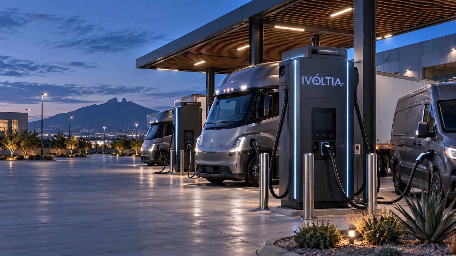 Application illustration
Confirm battery voltage, charging curve, connector, current and thermal requirements.
Plan turning radius, trailer length, through-bays, cable reach and equipment protection.
Test usable energy within the actual work window, including simultaneous vehicles and thermal derating.
YOUR OPERATING GOALS
We plan charging around vehicle routes, shift changes, available stopping time and site power. The result is a system that fits the fleet’s daily operation.
Power and connector count follow route energy and available dwell.
Cable reach, dispenser position, turning radii and collision protection are engineered together.
Modular cabinets and service access reduce the operational impact of maintenance.
The design defines what capacity remains available during a component or connector outage.
CONFIGURATION OPTIONS
The right system depends on energy per vehicle, voltage window, charge curve, simultaneous demand and the cost of a missed departure.
| Application | Configuration | Selection rationale |
|---|---|---|
| Bus or truck overnight depot | 120–240 kW integrated DC or shared distributed system | Scheduled departures allow controlled overnight allocation. |
| Opportunity charging between runs | 240–720 kW distributed DC | Central power can serve several dispensers and priority vehicles. |
| Mining, port or off-highway equipment | Application-specific high-power architecture | Environment, connector handling and duty cycle require project validation. |
| Future megawatt-class operation | Phased electrical backbone up to specialized 4.5 MW systems | Early reservation avoids rebuilding grid and civil infrastructure. |
FROM DESIGN TO HANDOVER
Battery, connector, voltage range, maximum current and charge curve.
Routes, payload, climate, arrival state of charge, dwell and reserve.
Grid, transformers, switchgear, protection, harmonics and site limits.
Bays, circulation, cable management, impact protection and service access.
Test vehicles, communications, sustained power, alarms and recovery procedures.
YOUR QUESTIONS, ANSWERED
Practical answers about Heavy-duty transport. No guesswork.
Ask about your project10 questions
When a large battery must receive substantial energy inside a very short dwell window and the vehicle can accept that power.
No. Output depends on configuration, number of dispensers, vehicle acceptance, voltage, temperature and active power-allocation rules.
It can share central power across several bays, reduce dispenser footprint and support staged expansion.
We identify critical departures, acceptable reduced capacity and which modules, connectors or communication paths must remain available.
Temperature, dust, water, altitude, corrosion, ventilation and impact exposure can affect equipment and derating.
Yes as a separate energy study. Their value depends on tariff, load profile, interconnection, space and operating objective.
We match the selected vehicle’s connector, voltage range and charging requirements to the equipment. The project proposal specifies the interface configuration and vehicle-integration tests.
Opportunity charging can be assessed when location, safety conditions and the usable dwell window allow it. Validate the operating process rather than counting the entire scheduled stop as charging time.
Not automatically. Current, cable design, temperature and sustained output requirements determine the choice. Confirm thermal conditions for the selected hardware.
Test the target vehicle, interface, voltage, sustained output, simultaneous charging and fault recovery under agreed conditions. Record the results in the handover documentation.
No matching question. Try another word or contact our team.
YOUR NEXT PROJECT
Your vehicles. Your site. Your operating goals. Start a conversation around the system you actually need.